- Sign In
- |
- Sign Up
- |
- My Quote (0)
- |
- CART (0)


Quality Tools for Professionals
Quality Tools for Professionals
Built around the True RMS industrial multimeter, this combo kit solves problems fast and deliver accurate and advanced troubleshooting capabilities that can handle complex signals. The kit includes accessories that increase the productivity of electricians.
Built around the True RMS industrial multimeter, this combo kit solves problems fast and deliver accurate and advanced troubleshooting capabilities that can handle complex signals. The kit includes accessories that increase the productivity of electricians.
Identifies complex signal problems fast
Provides the resolution and accuracy to efficiently troubleshoot motor drives, plant automation, power distribution, and electromechanical equipment. On top of that, this industrial multimeter effectively performs in loud, high energy, and high altitude locations. Features a low pass filter which supports precise frequency measurements on VFDs and acquires intermittents as quickly as 250 µS.
Use this multimeter to measure AC currents up to 10 A directly. Also, features a built-in thermometer that enables you to take temperature readings without having to carry a separate instrument and more. Plus, comes with a bright, two-level backlit display which allows you to see the results better in dim light.
Electrical safety
All inputs are protected to the 2nd edition of ANSI/ISA S82.01 and EN61010-1 CAT IV 600 V and CAT III, 1000 V. They can withstand impulses in excess of 8.000 V and reduce risks related to surges and spikes.
Correctly measure pulse-width modulated motor drive signals
Until now, there hasn't been a multimeter able to accurately measure adjustable speed drives. Although, this industrial multimeter is designed specifically to handle these complex signals. Think of the potential productivity you'll gain by taking the guesswork out of drive system troubleshooting. Measurements are correct each and every time.
Features
Applications
How to choose the best DMM for your job?
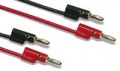
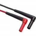
Multimeter Selection GuideFluke TL224 SureGrip™ Silicone Insulated Test Leads
Features
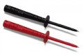
Fluke AC220 SureGrip™ Alligator Clips
Features
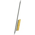
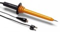
Fluke TL238 SureGrip™ Test Lead Set for High Energy Environments
Features
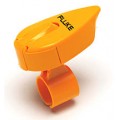
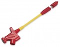
Fluke TPAK ToolPak Magnetic Meter Hanger
Take hands-free measurements with this magnetic meter hanger. The kit allows you to hang your meter in a variety of ways—including on nails, hooks and many other objects—solving any hanging and positioning problem you may face.
Please note that this product doesn't clip into the Fluke T6 Series like it does for other Fluke meters. Instead, you must simply feed the Velcro loop through the slot on the back of the T6 and Velcro it together.
Features
Fluke 80BK-A Integrated DMM Temperature Probe
Features
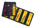
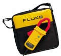
Fluke C35 Soft Carrying Case
Dimensions: 8.7 x 5.5 x 2.6" (220 x 140 x 65 mm)
Today’s thermal imagers have become a realistic solution for everyday electrical maintenance as they are rugged, easy to use, and much more affordable than even just a few years ago. It's a straight-forward process, where a qualified technician or electrician points the thermal imager at the equipment in question and scans the immediate area, looking for unexpected hot spots. The imager produces a live image of the heat emitted from the equipment and with the quick squeeze of the trigger, a thermal image is captured. When the inspection is complete, the image is uploaded to a computer, Apple®, iPhone® or iPad® for closer analysis, reporting, and future trending.
There are a few basic how-tos to consider... electrical load, safety, and emissivity. In this application note, we walk you through these, as well as the Top 5 Checklist, and much more.
Read the Application Note
| Voltage DC | Max voltage: 1000 V Accuracy: ±(0.05% + 1) Maximum resolution: 10 µV |
| Voltage AC | Max voltage: 1000 V Accuracy: ±(0.7% + 2) True RMS AC bandwidth: 20 kHz with low pass filter; 3 db @ 1 kHz Maximum resolution: 0.1 mV |
| Current DC | Maximum amps: 10 A (20 A for 30 seconds maximum) Amps accuracy: ±(0.2% + 2) Maximum resolution: 0.01 µA |
| Current AC | Maximum amps: 10 A (20 A for 30 seconds maximum) Amps accuracy: ±(1.0% + 2) True RMS Maximum resolution: 0.1 µA |
| Resistance | Maximum resistance: 50 MΩ Accuracy: ±(0.2% + 1) Maximum resolution: 0.1 Ω |
| Capacitance | Maximum capacitance: 9999 µF Accuracy: ±(1% + 2) Maximum resolution: 0.01 nF |
| Frequency | Maximum frequency: 200 kHz Accuracy: ±(0.005% + 1) Maximum resolution: 0.01 Hz |
| Temperature Measurement | -328 to 1994°F (-200 to 1090°C) excluding probe |
| 80 BK Temperature Probe | -40 to 500°F (-40 to 260°C), 2.2°C or 2% whichever is greater |
| Operating Temperature | -4 to 131°F (-20 to 55°C) |
| Storage Temperature | -40 to 140°F (-40 to 60°C) |
| Operating Altitude | 6561' (2000 m) |
| Dimensions | 7.9 x 3.9 x 2.05" (201 x 98 x 52 mm) with Holster |
| Weight | 0.8 lb (355 g) |
| Battery life | Alkaline approximately 400 h typical, without backlight |

Solve problems fast and deliver accurate and advanced troubleshooting capabilities that can handle complex signals. Additionally, this industrial multimeter with temperature is ideal for troubleshooting motor drives, plant automation, power distribution, and electromechanical equipment.

Provides convenience and variety for test lead configurations by attaching clips, hooks, and grabbers as needed.

Designed to improve steadiness with rubber overmolded surfaces and finger-hugging curves. For use with TL222 and TL224 test leads.

Designed for high energy environments, this kit comes equipped with the TP238, TP280, and TL224.

Hang your meter in a variety of ways for convenient hands-free operation. Attaches to most Fluke meters.

Compatible with Fluke DMMs with temperature measurement functions.

The top opens laterally to allow use of test tool without removing it from the case and includes a Velcro® strap to secure the test tool. It is made of durable polyester 600D.
 In the past, motor repair meant dealing with traditional three-phase motor failures that were largely the result of water, dust, grease, failed bearings, misaligned motor shafts, or just plain old age. But motor repair has changed in a big way with the introduction of electronically controlled motors, more commonly referred to as adjustable speed drives (ASDs). These drives present a unique set of measurement problems that can vex the most seasoned pro. Thanks to new technology, now for the first time you can take accurate electrical measurements with a DMM during the installation and maintenance of a drive and diagnose bad components and other conditions that may lead to premature failure.

Technicians use many different methods to troubleshoot an electrical circuit, and a good troubleshooter will always find the problem - eventually. The trick is tracking it down quickly and keeping downtime to a minimum. The most efficient troubleshooting procedure begins at the motor and then works systematically back to the electrical source, looking for the most obvious problems first. A lot of time and money can be wasted replacing perfectly good parts when the problem is simply a loose connection. As you go, take care to take accurate measurements. Nobody takes inaccurate measurements on purpose, but it's easy to do, especially when working in a high-energy, noisy environment like an ASD. Likewise, choosing the right test tools for troubleshooting the drive, the motor, and the connections are of utmost importance. This is especially true when taking voltage, frequency, and current measurements on the output side of the motor drive. But until now, there hasn't been a digital multimeter on the market able to accurately measure ASDs. Incorporates a selectable low pass filter* that allows for accurate drive output measurements that agree with the motor drive controller display indicator. Now, technicians won't have to guess whether the drive is operating correctly and delivering the correct voltage, current, or frequency for a given control setting.
Input side measurements
Any good quality True RMS multimeter can verify proper input power to an ASD. The input voltage readings should be within 1% of one another when measured from phase to phase with no load. A significant unbalance may lead to erratic drive operation and should be corrected when discovered.

Output side measurements
On the flip side, a regular True RMS multimeter can't reliably read the output side of a pulse width modulated (PWM) motor drive, because the ASD applies pulse width modulated nonsinusoidal voltage to the motor terminals. A True RMS DMM reads the heating effect of the non-sinusoidal voltage applied to the motor, while the motor controller's output voltage reading only displays the RMS value of the fundamental component (typically from 30 Hz to 60 Hz). The causes of this discrepancy are bandwidth and shielding. Many of today's True RMS digital multimeters have bandwidths out to 20 kHz or more, causing them to respond not only to the fundamental component, which is what the motor responds to but to all of the high-frequency components generated by the PWM drive. And if the DMM isn't shielded for high-frequency noise, the drive controller's high noise levels make the measurement discrepancies even more extreme. With the bandwidth and shielding issues combined, many True RMS meters display readings as much as 20 to 30% higher than what the drive controller is indicating. The incorporated selectable low pass filter allows troubleshooters to take accurate voltage, current, and frequency measurements on the output side of the drive at either the drive itself or the motor terminals. With the filter selected, the readings for both voltage and frequency (motor speed) should agree with the associated drive control display indications, if available. The low pass filter also allows for accurate current measurements when used with Hall-effect type clamps. All of these measurements are especially helpful when taking measurements at the motor location when the drive's displays are not in view.
Taking safe measurements
Before taking any electrical measurements, be sure you understand how to take them safely. No test instrument is completely safe if used improperly, and many test instruments are not appropriate for testing adjustable speed drives. Also, make sure to use the appropriate personal protective equipment (PPE) for your specific working environment and measurements. If at all possible, never work alone.


Safety ratings for electrical test equipment
ANSI and the International Electrotechnical Commission (IEC) are the primary independent organizations that define safety standards for test equipment manufacturers. The IEC 61010 second edition standard for test equipment safety states two basic parameters: a voltage rating and a measurement category rating. The voltage rating is the maximum continuous working voltage the instrument is capable of measuring. The category ratings depict the measurement environment expected for a given category. Most three-phase ASD installations would be considered a CAT III measurement environment, with power supplied from either 480V or 600V distribution systems. When using a DMM for measurements on these high-energy systems, make sure it's rated at a minimum for CAT III 600V and preferably for CAT IV 600V/CAT III 1000V. The category rating and voltage limit are typically found on the front panel, at the input terminals. Dual-rated CAT IV 600V and CAT III 1000V. Refer to the ABC's of DMM Safety* from Fluke for additional information on category ratings and taking safe measurements.
Now let's put the multimeter to the test. The measurements in the following procedure are designed to be made on a 480 volt 3 phase drive control at the control panel terminal strips. These procedures would also be valid for lower voltage 3 phase drives powered by either single or 3 phase supply voltages. For these tests, the motor is running at 50 Hz.
Input voltage
To measure the ac voltage supply to the input side of the drive at the drive:
Input current
Measuring the input current generally requires a current clamp accessory. In most cases, either the input current exceeds the maximum current measurable by the current function, or it isn't practical to "break the circuit" to take an in-line series current measurement. Regardless of clamp type, insure that all readings are within 10% of each other for proper balance.
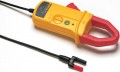
Transformer type clamp (i200, 80i-400, 80i-600A)
Hall Effect type (AC/DC) clamp (i410,i-1010)
Figure 1. Output voltage reading without using the low pass filter.


Figure 2. Output voltage reading with low pass filter enabled.

Output voltage
To measure the AC output voltage at either the drive or the motor terminals:
Figure 3. Output frequency (motor speed) without the low pass filter.


Figure 4. Output frequency (motor speed) using the low pass filter.

Motor speed (Output frequency using voltage as a reference)
To determine motor speed, simply take a frequency measurement while using the low pass filter. The measurement can be made between any two of the phase voltage or motor terminals.
Output current
TAs with input current, measuring the output current generally requires a current clamp accessory. Once again, regardless of clamp type, insure that all readings are within 10% of each other for proper balance.
Transformer type clamp (i200, 80i-400, 80i-600A)
Figure 5. Output current reading without using the low pass filter.


Figure 6. Output current reading with low pass filter enabled.

Hall Effect type (AC/DC) clamp (i410,i-1010)
Motor speed (Output frequency using current as a reference)
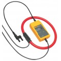
For motors that pull at least 20 amps of running current, motor speed can be determined by taking a frequency measurement with current clamps. Until now, noise issues have prevented accurate readings using hall effect type clamps. Here's how the low pass filter makes it possible.
Motor speed using a Hall Effect type (AC/DC) clamp (i410,i-1010)
Motor speed using a transformer type clamp (i200, 80i-400, 80i-600A)
DC Bus measurements
A healthy dc bus is a must for a properly operating motor drive. If the bus voltage is incorrect or unstable, the converter diodes or capacitors may be starting to fail. The DC bus voltage should be approximately 1.414 times the phase to phase input voltage. For a 480 volt input, the DC bus should be approximately 679 VDC. The DC bus is typically labeled as DC+, DC- or B+, Bon the drive terminal strip. To measure the DC bus voltage:
Click on a category to view a selection of compatible accessories with the Fluke 87V/E2 Industrial Electrician Combo Kit.


| Voltage DC | Max voltage: 1000 V Accuracy: ±(0.05% + 1) Maximum resolution: 10 µV |
| Voltage AC | Max voltage: 1000 V Accuracy: ±(0.7% + 2) True RMS AC bandwidth: 20 kHz with low pass filter; 3 db @ 1 kHz Maximum resolution: 0.1 mV |
| Current DC | Maximum amps: 10 A (20 A for 30 seconds maximum) Amps accuracy: ±(0.2% + 2) Maximum resolution: 0.01 µA |
| Current AC | Maximum amps: 10 A (20 A for 30 seconds maximum) Amps accuracy: ±(1.0% + 2) True RMS Maximum resolution: 0.1 µA |
| Resistance | Maximum resistance: 50 MΩ Accuracy: ±(0.2% + 1) Maximum resolution: 0.1 Ω |
| Capacitance | Maximum capacitance: 9999 µF Accuracy: ±(1% + 2) Maximum resolution: 0.01 nF |
| Frequency | Maximum frequency: 200 kHz Accuracy: ±(0.005% + 1) Maximum resolution: 0.01 Hz |
| Temperature Measurement | -328 to 1994°F (-200 to 1090°C) excluding probe |
| 80 BK Temperature Probe | -40 to 500°F (-40 to 260°C), 2.2°C or 2% whichever is greater |
| Operating Temperature | -4 to 131°F (-20 to 55°C) |
| Storage Temperature | -40 to 140°F (-40 to 60°C) |
| Operating Altitude | 6561' (2000 m) |
| Dimensions | 7.9 x 3.9 x 2.05" (201 x 98 x 52 mm) with Holster |
| Weight | 0.8 lb (355 g) |
| Battery life | Alkaline approximately 400 h typical, without backlight |
Solve problems fast and deliver accurate and advanced troubleshooting capabilities that can handle complex signals. Additionally, this industrial multimeter with temperature is ideal for troubleshooting motor drives, plant automation, power distribution, and electromechanical equipment.
Provides convenience and variety for test lead configurations by attaching clips, hooks, and grabbers as needed.
Designed to improve steadiness with rubber overmolded surfaces and finger-hugging curves. For use with TL222 and TL224 test leads.
Designed for high energy environments, this kit comes equipped with the TP238, TP280, and TL224.
Hang your meter in a variety of ways for convenient hands-free operation. Attaches to most Fluke meters.
Compatible with Fluke DMMs with temperature measurement functions.
The top opens laterally to allow use of test tool without removing it from the case and includes a Velcro® strap to secure the test tool. It is made of durable polyester 600D.
In the past, motor repair meant dealing with traditional three-phase motor failures that were largely the result of water, dust, grease, failed bearings, misaligned motor shafts, or just plain old age. But motor repair has changed in a big way with the introduction of electronically controlled motors, more commonly referred to as adjustable speed drives (ASDs). These drives present a unique set of measurement problems that can vex the most seasoned pro. Thanks to new technology, now for the first time you can take accurate electrical measurements with a DMM during the installation and maintenance of a drive and diagnose bad components and other conditions that may lead to premature failure.
Technicians use many different methods to troubleshoot an electrical circuit, and a good troubleshooter will always find the problem - eventually. The trick is tracking it down quickly and keeping downtime to a minimum. The most efficient troubleshooting procedure begins at the motor and then works systematically back to the electrical source, looking for the most obvious problems first. A lot of time and money can be wasted replacing perfectly good parts when the problem is simply a loose connection. As you go, take care to take accurate measurements. Nobody takes inaccurate measurements on purpose, but it's easy to do, especially when working in a high-energy, noisy environment like an ASD. Likewise, choosing the right test tools for troubleshooting the drive, the motor, and the connections are of utmost importance. This is especially true when taking voltage, frequency, and current measurements on the output side of the motor drive. But until now, there hasn't been a digital multimeter on the market able to accurately measure ASDs. Incorporates a selectable low pass filter* that allows for accurate drive output measurements that agree with the motor drive controller display indicator. Now, technicians won't have to guess whether the drive is operating correctly and delivering the correct voltage, current, or frequency for a given control setting.
Input side measurements
Any good quality True RMS multimeter can verify proper input power to an ASD. The input voltage readings should be within 1% of one another when measured from phase to phase with no load. A significant unbalance may lead to erratic drive operation and should be corrected when discovered.
Output side measurements
On the flip side, a regular True RMS multimeter can't reliably read the output side of a pulse width modulated (PWM) motor drive, because the ASD applies pulse width modulated nonsinusoidal voltage to the motor terminals. A True RMS DMM reads the heating effect of the non-sinusoidal voltage applied to the motor, while the motor controller's output voltage reading only displays the RMS value of the fundamental component (typically from 30 Hz to 60 Hz). The causes of this discrepancy are bandwidth and shielding. Many of today's True RMS digital multimeters have bandwidths out to 20 kHz or more, causing them to respond not only to the fundamental component, which is what the motor responds to but to all of the high-frequency components generated by the PWM drive. And if the DMM isn't shielded for high-frequency noise, the drive controller's high noise levels make the measurement discrepancies even more extreme. With the bandwidth and shielding issues combined, many True RMS meters display readings as much as 20 to 30% higher than what the drive controller is indicating. The incorporated selectable low pass filter allows troubleshooters to take accurate voltage, current, and frequency measurements on the output side of the drive at either the drive itself or the motor terminals. With the filter selected, the readings for both voltage and frequency (motor speed) should agree with the associated drive control display indications, if available. The low pass filter also allows for accurate current measurements when used with Hall-effect type clamps. All of these measurements are especially helpful when taking measurements at the motor location when the drive's displays are not in view.
Taking safe measurements
Before taking any electrical measurements, be sure you understand how to take them safely. No test instrument is completely safe if used improperly, and many test instruments are not appropriate for testing adjustable speed drives. Also, make sure to use the appropriate personal protective equipment (PPE) for your specific working environment and measurements. If at all possible, never work alone.
Safety ratings for electrical test equipment
ANSI and the International Electrotechnical Commission (IEC) are the primary independent organizations that define safety standards for test equipment manufacturers. The IEC 61010 second edition standard for test equipment safety states two basic parameters: a voltage rating and a measurement category rating. The voltage rating is the maximum continuous working voltage the instrument is capable of measuring. The category ratings depict the measurement environment expected for a given category. Most three-phase ASD installations would be considered a CAT III measurement environment, with power supplied from either 480V or 600V distribution systems. When using a DMM for measurements on these high-energy systems, make sure it's rated at a minimum for CAT III 600V and preferably for CAT IV 600V/CAT III 1000V. The category rating and voltage limit are typically found on the front panel, at the input terminals. Dual-rated CAT IV 600V and CAT III 1000V. Refer to the ABC's of DMM Safety* from Fluke for additional information on category ratings and taking safe measurements.
Now let's put the multimeter to the test. The measurements in the following procedure are designed to be made on a 480 volt 3 phase drive control at the control panel terminal strips. These procedures would also be valid for lower voltage 3 phase drives powered by either single or 3 phase supply voltages. For these tests, the motor is running at 50 Hz.
Input voltage
To measure the ac voltage supply to the input side of the drive at the drive:
Input current
Measuring the input current generally requires a current clamp accessory. In most cases, either the input current exceeds the maximum current measurable by the current function, or it isn't practical to "break the circuit" to take an in-line series current measurement. Regardless of clamp type, insure that all readings are within 10% of each other for proper balance.
Transformer type clamp (i200, 80i-400, 80i-600A)
Hall Effect type (AC/DC) clamp (i410,i-1010)
Figure 1. Output voltage reading without using the low pass filter.
Figure 2. Output voltage reading with low pass filter enabled.
Output voltage
To measure the AC output voltage at either the drive or the motor terminals:
Figure 3. Output frequency (motor speed) without the low pass filter.
Figure 4. Output frequency (motor speed) using the low pass filter.
Motor speed (Output frequency using voltage as a reference)
To determine motor speed, simply take a frequency measurement while using the low pass filter. The measurement can be made between any two of the phase voltage or motor terminals.
Output current
TAs with input current, measuring the output current generally requires a current clamp accessory. Once again, regardless of clamp type, insure that all readings are within 10% of each other for proper balance.
Transformer type clamp (i200, 80i-400, 80i-600A)
Figure 5. Output current reading without using the low pass filter.
Figure 6. Output current reading with low pass filter enabled.
Hall Effect type (AC/DC) clamp (i410,i-1010)
Motor speed (Output frequency using current as a reference)
For motors that pull at least 20 amps of running current, motor speed can be determined by taking a frequency measurement with current clamps. Until now, noise issues have prevented accurate readings using hall effect type clamps. Here's how the low pass filter makes it possible.
Motor speed using a Hall Effect type (AC/DC) clamp (i410,i-1010)
Motor speed using a transformer type clamp (i200, 80i-400, 80i-600A)
DC Bus measurements
A healthy dc bus is a must for a properly operating motor drive. If the bus voltage is incorrect or unstable, the converter diodes or capacitors may be starting to fail. The DC bus voltage should be approximately 1.414 times the phase to phase input voltage. For a 480 volt input, the DC bus should be approximately 679 VDC. The DC bus is typically labeled as DC+, DC- or B+, Bon the drive terminal strip. To measure the DC bus voltage:
Click on a category to view a selection of compatible accessories with the Fluke 87V/E2 Industrial Electrician Combo Kit.